Web / SNMP Intelligent Products
WSW-2400 24-Port Fast Ethernet SwitchTerminal Mode Management
There are two ways to access system terminal management screen. One is to connect a terminal to the console port on the switch via using a RS-232 serial cable. The other is to remote access the terminal management screen after typing IP address of the switch via Internet.
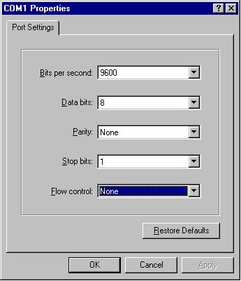
Note: To access system terminal management via console port, you must do some setting as following figure.
After the access to system terminal management, please key-in username and password (both factory default are " manager") to start to configure the switch.
After login, you can enter the main menu to configure each item via typing the letter, which is in the square bracket, on the command line.
In the main menu, you just need to press the “G” letter on the command line and you can enter into the "General Information" screen.

In the "General Information" screen, you can see all information of the management switch. Some information is default setting and some is result of your configuration in the next steps such as "Administration Information", "System MAC Address", "IP Address", "Subnet Mask and Router". If you want to return to the main menu, just press any key.
The "Basic Switch Configuration" screen allows you to set or modify the basic switch configuration such as:

The data you key-in will save after you press “ENTER”. If you want to enter in this screen, just press the letter “B” on the command line of the main menu.
1. System Administration ConfigurationThe “System Administration Configuration” screen allows you to set the administration information of the switch like:
- System Name
- System Location
- System Contact Information
If you want to leave this screen, press “Q” letter on the command line and it will back to the previous screen.
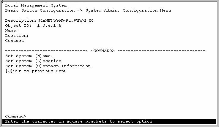
Table 3-1 is the detail description of the system administration configuration. Type the command letter on the command line and it will open the screen to configure when you want to configure the item.
Table 3-1 System Administration Configuration Description
Item Command
Description
System Name N
Set the name of the Switch.
Default: Empty
Range: The maximum length of this item is 50.System Location L
Set the location of the switch.
Default: Empty
Range: The maximum length of this item is 50.System Contact Information C
Set the relative information of the in change person.
Default: Empty
Range: The maximum length of this item is 50.2. System IP ConfigurationThe “System IP Configuration” screen allows you to set the IP information of the switch such as:
- IP Address
- Subnet Mask
- Gateway
- BOOTP Mode
If you want to leave this screen, press “Q” letter on the command line and it will back to the previous screen.
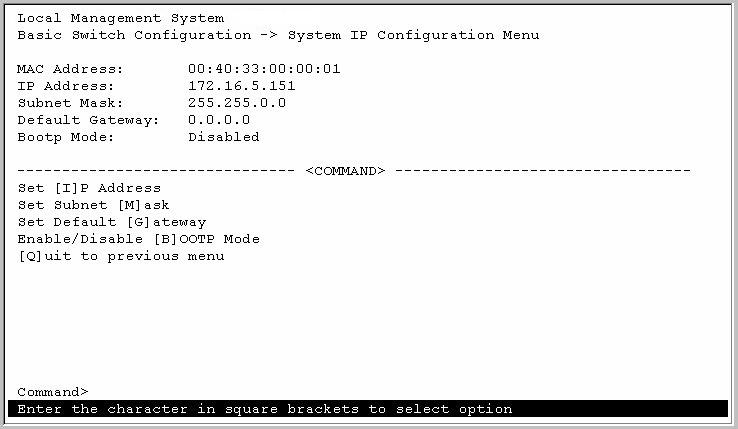
Table 3-2 is the detail description of the system administration configuration. Type the command letter on the command line and it will open the screen to configure when you want to configure the item.
Table 3-2 System IP Configuration Description
Item
Command
Description
IP Address I
Set the IP address of the switch.
Default Value: 0.0.0.0
Range: 4 decimal numbers and each on is separated by a dot.Subnet Mask M
Set the Subnet Mask address of the switch.
Default: 0.0.0.0
Range: 4 decimal numbers and each one is separated by a dot.Default Gateway G
Set the gateway address of the switch.
Default: 0.0.0.0
Range: 4 decimal numbers and each one are separated by a dot.Enable/Disable BOOTP Mode B
Allows you to enable or disable the BOOTP mode.
Default: Disable
Range: Enable, Disable3. SNMP ConfigurationThe “SNMP Configuration” screen allows you to set or modify the SNMP configuration parameters such as:
- Read Community
- Write Community
- Trap Receiver
- Auth. Trap
If you want to leave this screen, press “Q” letter on the command line and it will back to the previous screen.

Table 3-3 is the detail description of the system administration configuration. Type the command letter on the command line and it will open the screen to configure when you want to configure the item.
Table 3-3 SNMP Configuration Description
Item
Command
Description
Read Community R
Set the community string used for read SNMP operations.
Default: Public
Range: Maximum length for read community name is 20.Write Community W
Set the community string used for write SNMP operations.
Default: Private
Range: Maximum length for writes community name is 20.Enable/Disable Trap Receiver S
Enable or disable the trap receiver.
Default:
Range: Enable, DisableChange Trap Receiver Settings T
Allows you to modify the trap receiver settings such as IP address and community. Enable/Disable Auth. Trap A
Determines whether a trap will be sent when there is an SNMP authentication failure.
Default: Enable
Range: Enable, Disable4. Port ConfigurationThe “Port Configuration” screen allows you to set or modify the port configuration parameters such as:
- Port Status
- Port Mode
- Flow Control
If you want to leave this screen, press “Q” letter on the command line and it will be back to previous screen.

Table 3-4, 3-4-A are the detail description of the port configuration. Type the command letter on the command line and it will open the screen to configure when you want to configure the item.
Table 3-4 Port Configuration Description
Item
Command
Description
Next Page N
Allows you to view the status of port 13-24.
Previous Page P
Allows you to view the status of port 1-12. Change Port Settings S
Allows you to set or modify ports configuration like port status, port mode and port flow control. In this step, you have to choose one item then choose one port for setting. The setting will show on the Table 3-4-1. Table 3-4-A Change Port Settings Description
Item
Command
Description
Status S
Allows you to enable or disable the port. If you choose “Enable”, then the port can work normally. The port can’t receive or transmit data, even the port is connecting with the twist-pair cable, when you choose “Disable”.
Default: Enable
Range: Enable, DisableMode M
Allows you to choose the operating mode of the port
Default: Auto-negotiation
Range: Auto-negotiation, 10Mbps/half-duplex, 100Mbps/half-duplex, 10Mbps/full-duplex, 100Mbps/full-duplex.Flow Control F
Allows you to enable or disable flow control of ports.
Default: Disable
Range: Enable, Disable5. Spanning Tree ConfigurationThe “Spanning Tree Configuration” screen allows you to set or modify the spanning tree configuration parameters such as:
- Enable/Disable STP
- Bridge Priority
- Bridge Hello Time
- Bridge Maximum Age
- Bridge Forward Delay
- Spanning Tree Port Configuration
If you want to leave this screen, press “Q” letter on the command line and it will be back to previous screen.
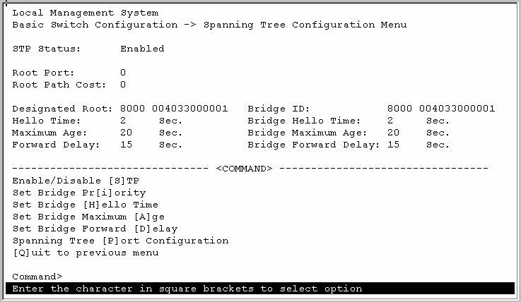
Table 3-5 is the detail description of the spanning tree configuration. Type the command letter on the command line and it will open the screen to configure when you want to configure the item.
Table 3-5 Spanning Tree Configuration
Item
Command
Description
Enable/Disable STP S
Allows you to enable or disable the spanning tree feature.
Default: Enable
Range: Enable, DisableBridge Priority I
Set the priority of the bridge. The spanning tree uses this parameter to determine the root bridge. When the bridge with the lowest bridge priority, it becomes the root bridge.
Default: 32768
Range: 0-65535Bridge Hello Time H
Set the bridge Hello Time that is the amount of time between transmissions of configuration Bridge Protocol Data Units that the root bridge is currently using.
Default: 2 seconds
Range: 1-10 secondsBridge Maximum Age A
Set the value specifies the maximum age that a Hello messages can attain before it is discarded.
Default: 20 seconds
Range: 6-40 secondsBridge Forward Delay D
Set the value specified the amount of time that the bridge ports remain in the Listening and Learning states before entering the Forwarding state.
Default: 15 seconds
Range: 4-30 secondsSpanning Tree Port Configuration P
Allows you to set or modify spanning tree ports configuration like priority and path cost. In this step, you have to choose one item then choose one port for setting. The setting will show on the Table 3-5-A. Table 3-5-A Spanning Tree Port Configuration Description
Item
Command
Description
Next Page N
Allows you to see the spanning tree information of port 13-24.
Previous Page P
Allows you to see the spanning tree information of port 1-12. Change Port Settings S
Allows you to set or modify spanning tree ports configuration like priority and path cost. In this step, you have to choose one item then choose one port for setting. The setting will show on the Table 3-5-B.
Table 3-5-B Change Port Setting Description
Item
Command
Description
Priority P
Set the parameter that prioritizes the port’s lowest path cost to the root. The spanning tree selects the path with the highest priority when one or more ports have the same path cost.
Default: 128
Range: 0-255Path Cost C
Set the parameter that determines the lowest path cost to the root.
Default: 10
Range: 0-1000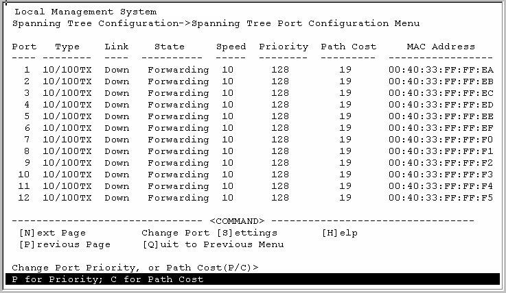 6. User Interface Configuration
The “User Interface Configuration” screen allows you to set the user interface configuration of the switch like:
- Console UI Time Out
- Telnet UI Time Out
- Enable/Disable Telnet Server
- Enable/Disable SNMP Agent
- Enable/Disable SNMP Web Server
- Change Administrator User Name
- Change Administrator Password
If you want to leave this screen, press “Q” letter on the command line and it will back to the previous screen.
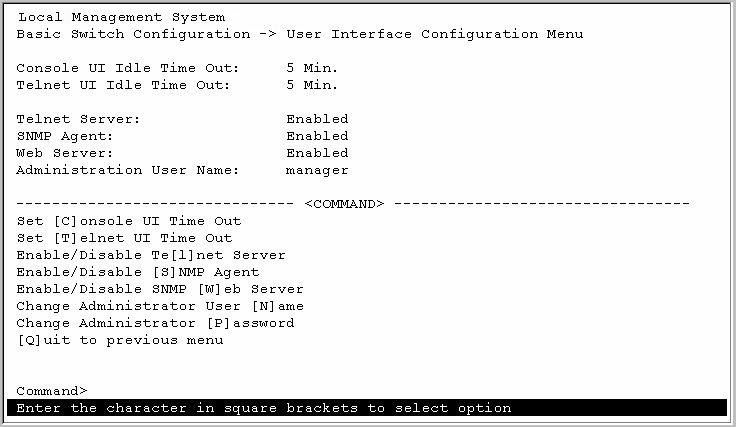
Table 3-6 is the detail description of the user interface configuration. Type the command letter on the command line and it will open the screen to configure when you want to configure the item.
Table 3-6 User Interface Configuration Description
Item
Command
Description
Console UI Time Out C
Default: 5 minutes
Range: 0-60 minutes, 0 means no timeoutTelnet UI Time Out T
Default: 5 minutes
Range: 0-60 minutesEnable/Disable Telnet Server L
Enable or disable the telnet server. If you choose disable, you can’t configure the switch through the telnet terminal.
Default: Enable
Range: Enable, DisableEnable/Disable SNMP Agent S
Enable or disable the SNMP agent. If you choose disable, you can’t configure the switch through the SNMP agent.
Default: Enable
Range: Enable, DisableEnable/Disable SNMP Web Server W
Enable or disable the SNMP web server. If you choose disable, you can’t configure the switch through the SNMP web server.
Default: Enable
Range: Enable, DisableChange Administrator User Name N
Modify the administrator user name of the switch.
Default: manager
Range: Maximum length for user name is 12.Change Administrator Password P
Modify the administrator user password of the switch.
Default: manager
Range: Maximum length for password is 12.
The “Advanced Switch Configuration” screen allows you to set or modify the advanced switch configuration such as:
- VLAN Management
- Trunk Configuration
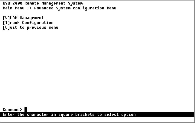
The data you key-in will save after you press “ENTER”. If you want to enter in this screen, just press the letter “A” on the command line of the main menu.
1. VLAN ManagementThis VLAN Management menu allows you to configure up to 4 port-based VLANs. Creating VLANs extends the broadcast domain and segment network traffic. Each port of the 24-port switch can be assigned to up to four VLAN. Once power on, every port is assigned to VLAN-1 as the default. Frames from the source port will only be forwarded to the destination ports within the same VLAN domain.
The “VLAN Management” screen allows you to set the VLAN configuration of the switch.
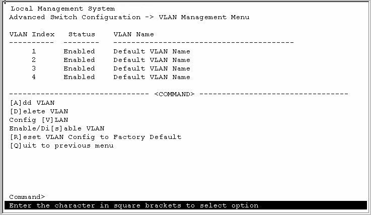
If you want to leave this screen, press “Q” letter on the command line and it will back to the previous screen.
Table 3-7 is the detail description of the VLAN management configuration. Type the command letter on the command line and it will open the screen to configure when you want to configure the item.
Table 3-7 VLAN Management Configuration Description
Item
Command
Description
Add VLAN A
Allows you to add the VLAN. You have to follow the steps to create a new VLAN:
- Choose the new VLAN index you want to create.
- Enter the VLAN name of the created VLAN.
- Enter the port member of the created VLAN.
- Enable or disable the created VLAN.
Delete VLAN D
Delete specified VLANs. All you need to do is choosing the VLAN index you want to delete. Press ENTER. Then the specified VLAN is deleted.
Config VLAN V
Allows you to configure the specified VLAN. The detail description is in the Table 3-7-A. Enable/Disable VLAN s
Allows you to enable or disable the VLANs.
Choose specified VLAN, then determine to enable or disable the VLAN.Reset VLAN config to Factory Default R
Allows you to reset VLAN configuration to Factory Default. 2.Trunk ConfigurationTable 3-7-A Configuration VLAN Description
Item
Command
Description
Change VLAN name N
Set the specified VLAN name.
Default: Default VLAN
Range: Maximum length for VLAN name is 32.Add/Delete VLAN port member M
Add or delete port member of specified VLAN.
Select VLAN S
The Trunk configuration allows you to times the bandwidth between the Switch and one non trunk-supported switch. The maximum bandwidh can up to 4 turnks for 800Mbps bandwidth. Before add a trunk, please disable the "Spanning Tree Protocol".
The following screen is the port trunk configuration screen.

To add a trunk, please "A" to add and select port number.Continue the steps for secord, third and fourth ports. Please be noted, Port#12 is a multi-funciton port, it is not allowed to set as a trunk link.
Then click on "S" to "Set the Status", "E" to enable, "D" to disable.
If you want to leave this screen, press “Q” letter on the command line and it will back to the previous screen.
Table 3-8 is the detail description of the port trunking configuration. Type the command letter on the command line and it will open the screen to configure when you want to configure the item.
Table 3-8 Port Trunking Configuration Description
Item
Command
Description
Add Trunk Port A
Set the Trunk Port.
Range: Port 1-24 (except: port 12)Remove Trunk Port R
Remove the Trunk Port.
Range: Port 1-24 (except: port 12)Set Trunk Status S
Allows you to rt or stop the port trunk function.
After enable the turnking, for example, in figure above, port 10 and port 11 becomes a trunk group. You are free to connect any standard switch to these two ports without fear of network loop. By contrast, you can double the bandwitdth between the two switches up to 400Mbps. Please be noted, the Switch only support one switch trunking. At the mean time, the connected switch should also disable its turnking capability if it does.
The “System Reboot” screen allows you to set or modify the system reboot configuration such as:
- Schedule Reboot Countdown
- Cancel Reboot Process
- Set Reboot Option
- Start Reboot Process
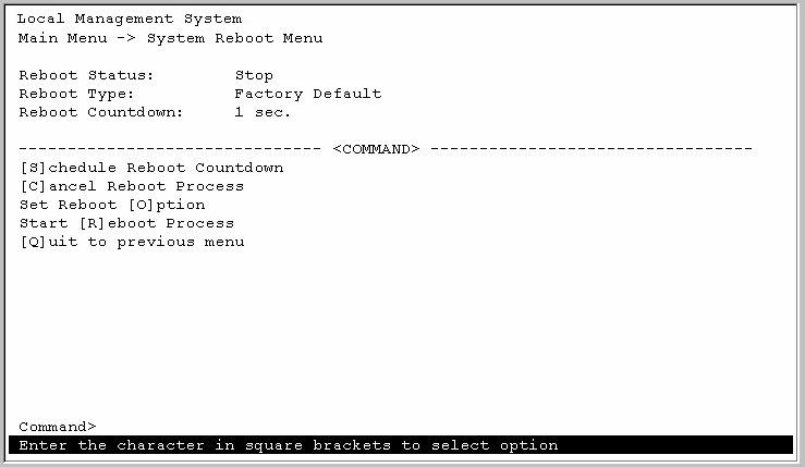
The data you key-in will save after you press “ENTER”. If you want to enter in this screen, just press the letter “R” on the command line of the main menu.
Table 3-9 is the detail description of the system reboot configuration. Type the command letter on the command line and it will open the screen to configure when you want to configure the item.
Table 3-9 System Reboot Configuration Description
Item
Command
Description
Schedule Reboot Countdown S
Set the countdown reboot option.
Default: 1 (Second)
Range: 1 ~ 60 secondCancel Reboot Process C
Cancel the countdown reboot process.
Set Reboot Option O
Set the reboot option.
Normal: All configured data will be saved after you reboot the system.
Factory Default: All switch configurations will return to the Factory Default after you reboot the system.
Factory Default Except IP: All switch configurations will return to the Factory Default except the IP address after you reboot the system.
Default: Normal
Range: Normal, Factory Default, Factory Default Except IPStart Reboot Process R
Allows you to reboot the system right now.
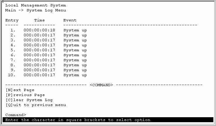
The System Log screen lets you to view the log of the switch system. You may choose “Next Page” or “Previous Page” to see all ports logs. You also can choose “Clear system log” to clear all ports logs. The following screen is the System Log screen.
There is a software upgrade function provided in the switch. This function lets you upgrade the software. When you want to upgrade the software, you just need to press “U” letter on the command line of the main menu.
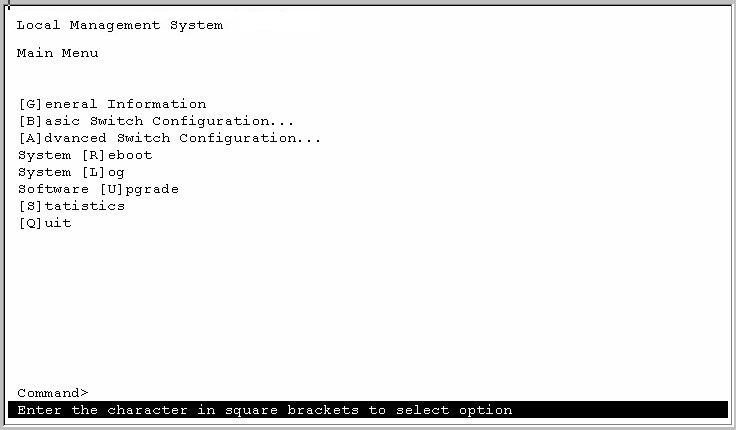
Table 3-10 is the detail description of the system log configuration. Type the command letter on the command line and it will open the screen to configure when you want to configure the item.
Table 3-10 System Log Configuration Description
Item
Command
Description
Set Remote Server IP Address S
Set the IP address of the remote TFTP server, which you will download the upgraded software.
Default: 0.0.0.0
Range: 4 decimal numbers and each on is separated by a dot.Set Remote File Name F
Set the file name, which you will download the upgraded software.
Default: Empty
Range: Maximum length of the file name is 30.Download Image File and Reboot D
Allows you to download the file.
Set Retry Count R
Set the retry count time.
Default: 5
Range: 1-20
The Statistics screen lets you to view the statistic data of the specified port of the switch system. You may choose “Select Port”, “Next Port” or “Previous Port” to see all ports statistic data such as: receive packages, receive bytes, well broadcast and so on. The following screen is the System Log screen.

| [Top of this Chapter] |
Copyright (c) 2000, Planet Technology
Corp.
![]()
