Web / SNMP MANAGEABLE
SGSW-2403
24-Port 10/100/1000Mbps stackable switch
Using the System Configuration Program
Once a direct connection to the serial port or a Telnet connection is established, the login screen for the on-board configuration program appears as shown below.

If this is your first time to log into the configuration program, then the default user names are "admin" and "guest" with no password. The administrator has Read/ Write access to all configuration parameters and statistics. While the guest has Read Only access to the management program.
You should define a new administrator password,
record it and put it in a safe place. Select Console Login Configuration from
the Management Setup Menu and enter a new password for the administrator. Note
that passwords can consist of up to 11 alphanumeric characters and are not case
sensitive.
NOTES: |
|
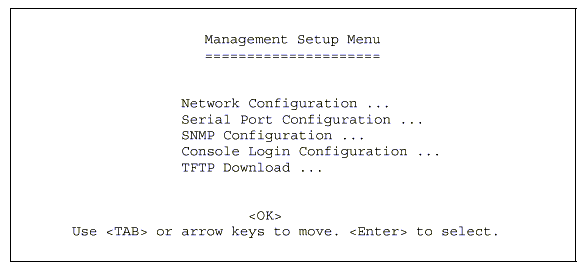
After you enter the user name and password, you will have access to the system configuration program as illustrated by the following menu hierarchy:

*
Not implemented in this firmware release.
With the system configuration program you can
define system parameters, manage and control the switch, the connected stack
and all its ports, or monitor network conditions. The figure below of the Main
Menu and the following table briefly describe the selections available from
this program.
NOTES: |
Options for the currently selected item are displayed in the highlighted area at the bottom of the interface screen. |

Menu |
Description |
|
System Information Menu |
||
|
System Information |
Provides basic system description, including contact information. |
|
Switch Information |
Shows hardware/firmware version numbers, power status, and expansion modules used in the stack. |
Management Setup Menu |
||
|
Network Configuration |
Includes IP setup, Ping facility, HTTP (Web agent) setup, Telnet configuration, and MAC address. |
|
Serial Port Configuration |
Sets communication parameters for the serial port, including management mode, baud rate, console time-out, and screen data refresh interval. |
|
SNMP Configuration |
Activates traps; and configures communities and trap managers. |
|
Console Login Configuration |
Sets user names and passwords for system access, as well as the invalid password threshold and lockout time. |
|
TFTP Download |
Downloads new version of firmware to update your system (in-band). |
Device Control Menu |
||
|
Port Configuration |
Enables any port, enables/disables flow control, and sets communication mode to auto-negotiation, full duplex or half duplex. |
|
Port Information |
Displays operational status, including link state, flow control method, and duplex mode. |
|
Spanning Tree Configuration |
Enables Spanning Tree Algorithm; also sets parameters for hello time, maximum message age, switch priority, and forward delay; as well as port priority, path cost, and fast forwarding. |
|
Spanning Tree Information |
Displays full listing of parameters for the Spanning Tree Algorithm. |
|
Port Mirror Configuration |
Sets the source and target ports for mirroring. |
|
Port Trunking Configuration |
Specifies ports to group into aggregate trunks. |
|
IGMP Configuration |
Configures IGMP multicast filtering. |
|
Extended Bridge Configuration |
Displays/configures extended bridge capabilities provided by this switch. |
|
802.1P Configuration |
Configures default port priorities and queue assignments. |
|
802.1Q VLAN Base Information |
Displays basic VLAN information, such as VLAN version number and maximum VLANs supported. |
|
802.1Q VLAN Current Table Information |
Displays VLAN groups and port members. |
|
802.1Q VLAN Static Table Configuration |
Configures VLAN groups via static assignments, including setting port members, or restricting ports from being dynamically added to a port by the GVRP protocol. |
|
802.1Q VLAN Port Configuration |
Displays/configures port-specific VLAN settings, including PVID, ingress filtering, and GVRP. |
|
Port GMRP Configuration* |
Configures GMRP multicast filtering. |
Network Monitor Menu |
||
|
Port Statistics |
Displays statistics on network traffic passing through the selected port. |
|
RMON Statistics |
Displays detailed statistical information for the selected port such as packet type and frame size counters. |
|
Unicast Address Table |
Provides full listing for unicast addresses, as well as search and clear functions. |
|
Multicast Address Registration Table* |
Provides full listing for multicast addresses, as well as search and clear functions. |
|
IP Multicast Registration Table |
Displays all the multicast groups active on this switch, including multicast IP addresses and corresponding VLAN IDs. |
|
Static Unicast Address Table Configuration |
Used to manually configure host MAC addresses in the unicast table. |
|
Static Multicast Address Table Configuration* |
Used to manually configure host MAC addresses in the unicast table. |
|
Static Multicast Address Table Configuration* |
Used to manually configure host MAC addresses in the multicast table. |
|
Restart System |
Restarts system with options to use POST, or to retain factory defaults, IP settings, or user authentication settings. |
|
ExitRestart System |
Exits the configuration program.. |
Device Control Menu |
||
|
Port Configuration |
Enables any port, enables/disables flow control, and sets communication mode to auto-negotiation, full duplex or half duplex. |
|
Port Information |
Displays operational status, including link state, flow control method, and duplex mode. |
|
Spanning Tree Configuration |
Enables Spanning Tree Algorithm; also sets parameters for hello time, maximum message age, switch priority, and forward delay; as well as port priority, path cost, and fast forwarding. |
|
Spanning Tree Information |
Displays full listing of parameters for the Spanning Tree Algorithm. |
|
Port Mirror Configuration |
Sets the source and target ports for mirroring. |
|
Port Trunking Configuration |
Specifies ports to group into aggregate trunks. |
|
IGMP Configuration |
Configures IGMP multicast filtering. |
|
Extended Bridge Configuration |
Displays/configures extended bridge capabilities provided by this switch. |
|
802.1P Configuration |
Configures default port priorities and queue assignments. |
|
802.1Q VLAN Base Information |
Displays basic VLAN information, such as VLAN version number and maximum VLANs supported. |
|
802.1Q VLAN Current Table Information |
Displays VLAN groups and port members. |
|
802.1Q VLAN Static Table Configuration |
Configures VLAN groups via static assignments, including setting port members, or restricting ports from being dynamically added to a port by the GVRP protocol. |
|
802.1Q VLAN Port Configuration |
Displays/configures port-specific VLAN settings, including PVID, ingress filtering, and GVRP. |
|
Port GARP Configuration* |
Configures settings used in multicast filtering. |
|
Port GMRP Configuration* |
Configures GMRP multicast filtering. |
Network Monitor Menu |
||
|
Port Statistics |
Displays statistics on network traffic passing through the selected port. |
|
RMON Statistics |
Displays detailed statistical information for the selected port such as packet type and frame size counters. |
|
Unicast Address Table |
Provides full listing for unicast addresses, as well as search and clear functions. |
|
Multicast Address Registration Table* |
Provides full listing for multicast addresses, as well as search and clear Provides full listing for multicast addresses, as well as search and clear |
|
IP Multicast Registration Table |
Displays all the multicast groups active on this switch, including multicast IP addresses and corresponding VLAN IDs. |
|
Static Unicast Address Table Configuration |
Used to manually configure host MAC addresses in the unicast table. |
|
Static Multicast Address Table Configuration* |
Used to manually configure host MAC addresses in the multicast table. |
Restart System |
Restarts system with options to use POST, or to retain factory defaults, IP settings, or user authentication settings. |
|
Exit |
Exits the configuration program. |
|
* Not implemented in this firmware release.
Use the System Information Menu to display a
basic description of the switch,
including contact information, and hardware/firmware versions.

Menu |
Description |
System Information |
Provides basic system description, including contact information. |
Switch Informationn |
Shows hardware/firmware version numbers, power status, and expansion modules used in the stack. |
5.3.1 Displaying System Information
Use the System Information screen to display descriptive information about the switch, or for quick system identification as shown in the following figure and table.

Parameter |
Description |
System Description |
System hardware description. |
System Object ID |
MIB II object identifier for switch�s network management subsystem. |
System Up Time |
Length of time the current management agent has been running. (Note that the first value is 1/100 seconds.) |
System Name* |
Name assigned to the switch system. |
System Contact* |
Contact person for the system. |
System Location* |
Specifies the area or location where the system resides. |
* Maximum string length is 99, but the screen only displays 45 characters. You can use the arrow keys to browse the whole string.
5.3.2 Displaying Switch Version Information
Use the Switch Information screen to display hardware/firmware version numbers for the main board, as well as the power status.

Parameter |
Description |
|
Main Board |
||
|
Hardware Version |
Hardware Version |
|
Firmware Version |
System firmware version in ROM. |
|
Serial Number |
The serial number of the main board. |
|
Port Number |
Number of built-in ports. |
|
Internal Power Status |
Indicates if the primary power is active or inactive. |
|
Redundant Power Status |
Indicates if the redundant power is active or inactive. |
|
Expansion Slot 1 |
Shows module type if inserted (100BASE-FX or 1000BASE-SX). |
|
Expansion Slot 2* |
Shows module type if inserted (100BASE-FX or 1000BASE-SX or 4GB Stack). |
Agent Module |
||
|
Hardware Version |
Hardware version of the agent module. |
|
POST ROM Version |
Power-On Self-Test version number. |
|
Firmware Version |
Firmware version of the agent module. |
|
SNMP Agent |
Shows if this module is Master or Backup Master. |
After initially logging onto the system, adjust the communication parameters for your console to ensure a reliable connection (Serial Port Configuration). Specify the IP addresses for the switch (Network Configuration / IP Configuration), and then set the Administrator and User passwords (Console Login Configuration). Remember to record them in a safe place. Also set the community string which controls access to the on-board SNMP agent via in-band management software (SNMP Configuration). The items provided by the Management Setup Menu are described in the following sections.
Menu |
Description |
Network Configuration |
Includes IP setup, Ping facility, HTTP (Web agent) setup, Telnet configuration, and MAC address. |
Serial Port Configuration |
Sets communication parameters for the serial port, including management mode, baud rate, console time-out, and screen data refresh interval. |
SNMP Configuration |
Activates traps; and configures communities and trap managers. |
Console Login Configuration |
Sets user names and passwords for system access, as well as the invalid password threshold and lockout time. |
TFTP Download |
Downloads new version of firmware to update your system (in-band). |
5.4.1 Changing the Network Configuration
Use the Network Configuration menu to set the bootup option, configure the switch's Internet Protocol (IP) parameters, enable the on-board Web agent, or to set the number of concurrent Telnet sessions allowed. The screen shown below is described in the following table.

Parameter |
Description |
IP Configuration |
Screen used to set the bootup option, or configure the switch�s IP parameters. |
IP Connectivity Test (Ping) |
Screen used to test IP connectivity to a specified device. |
HTTP Configuration |
Screen used to enable the Web agent. |
MAX Number of Allowed Telnet Sessions |
The maximum number of Telnet sessions allowed to simultaneously access the agent module. |
MAC Address |
Physical address of the agent module. |
Use the IP Configuration screen to set the bootup option, or configure the switch�s IP parameters. The screen shown below is described in the following table.

Parameter |
Description |
Interface Type |
Indicates IP over Ethernet. |
IP Address |
IP address of the stack you are managing.
The system supports SNMP over UDP/ IP transport protocol. In
this environment, all systems on the Internet, such as network
interconnection devices and any PC accessing the agent module
(or running AccView) must have an IP address. |
Subnet Mask |
Subnet mask of the switch you have selected. This mask identifies the host address bits used for routing to specific subnets. |
Default Gateway |
Gateway used to pass trap messages from the system�s agent to the management station. Note that the gateway must be defined if the management station is located in a different IP segment. The default value is null. |
IP State |
Specifies whether IP functionality is
enabled via manual configuration, or set by Boot Protocol (BOOTP).
Options include: |
5.4.1.2 IP Connectivity Test (Ping)
Use the IP Connectivity Test to see if another site on the Internet can be reached. The screen shown below is described in the following table.

Parameter |
Description |
IP Address |
IP address of the site you want to ping. |
Test Times |
The number of ICMP echo requests to send
to the specified site. |
Interval |
The interval (in seconds) between pinging
the specified site. |
Success/Failure |
The number of times the specified site has responded or not to pinging. |
Use the HTTP Configuration screen to enable/disable the on-board Web agent, and to specify the TCP port that will provide HTTP service. The screen shown below is described in the following table.

Parameter |
Description |
HTTP Server |
Enables/disables access to the on-board Web agent. |
HTTP Port Number |
Specifies the TCP port that will provide
HTTP service. |
5.4.2 Configuring the Serial Port
You can access the on-board configuration program by attaching a VT100 compatible device to the switch�s serial port. (For more information on connecting to this port, see "Required Connections" .) The communication parameters for this port can be accessed from the Serial Port Configuration screen shown below and described in the following table.

Parameter |
Default |
Description |
Management Mode |
Console Mode |
Indicates that the console port settings are for direct console connection. |
Baud rate |
19200 |
The rate at which data is sent between
devices. |
Data bits |
8 bits |
Sets the data bits of the RS-232 port. |
Stop bits |
1 bit |
Sets the stop bits of the RS-232 port. |
Parity |
None |
Sets the parity of the RS-232 port. |
Time-Out |
10 minutes |
If no input is received from the attached
device after this interval, the current session is automatically
closed. |
Auto Refresh |
5 seconds |
Sets the interval before a console session
will auto refresh the console information, such as Spanning
Tree Information, Port Configuration, Port Statistics, and RMON
Statistics. |
5.4.3 Assigning SNMP Parameters
Use the SNMP Configuration screen to display and modify parameters for the Simple Network Management Protocol (SNMP). The switch includes an on-board SNMP agent which monitors the status of its hardware, as well as the traffic passing through its ports. A computer attached to the network, called a Network Management Station (NMS), can be used to access this information. Access rights to the on-board agent are controlled by community strings. To communicate with the switch, the NMS must first submit a valid community string for authentication. The options for configuring community strings and related trap functions are described in the following sections.

Parameter |
Description |
Send Authentication Fail Traps |
Issue a trap message to specified IP trap managers whenever authentication of an SNMP request fails. (The default is disabled.) |
SNMP Communities |
Assigns SNMP access based on specified strings. |
IP Trap Managers |
Specifies management stations that will receive authentication failure messages or other trap messages from the switch. |
5.4.3.1 Configuring Community Names
The following figure and table describe how to configure the community strings authorized for management access. Up to 5 community names may be entered
.
Parameter |
Description |
Community Name |
A community entry authorized for management
access. |
Access |
Management access is restricted to Read Only or Read/Write. |
Status |
Sets administrative status of entry to
enabled or disabled. |
NOTES: |
The default community string is "public" with Read/Write access. It is recommended to create a new community for the switch with R/W capability with the SNMP Management Software like SNMPc. The change the default to Read Only ! |
5.4.3.2 Configuring IP Trap Managers
The following figure and table describe how to specify management stations that will receive authentication failure messages or other trap messages from the switch. Up to 5 trap managers may be entered.

Parameter |
Description |
IP Address |
IP address of the trap manager. |
Community Name |
A community specified for trap management access. |
Status |
Sets administrative status of selected entry to enabled or disabled. |
5.4.4 Console Login Configuration
Use the Management Setup: Console Login Configuration to restrict management access based on specified user names and passwords, or to set the invalid password threshold and time-out. There are two user types, Administrator and Guest. Only the Administrator has write access for parameters governing the SNMP agent. You should therefore assign a user name and password to the Administrator as soon as possible, and store it in a safe place. (If for some reason your password is lost, or you cannot gain access to the System Configuration Program, contact PLANET Technical Support for assistance.) The parameters shown on this screen are indicated in the following figure and table.

Parameter |
Default |
Description |
Password Threshold |
3 |
Sets the password intrusion threshold
which limits the number of failed logon attempts. |
Lock-out Time |
0 |
The time (in seconds) the management
console will be disabled due to an excessive number of failed
logon attempts. |
Admin* |
name: admin password: null |
password: null Administrator has access privilege of Read/Write for all screens. |
* Passwords can consist of up to 11 alphanumeric characters and are not case sensitive.
5.4.5 Downloading System Software
5.4.5.1 Using TFTP to Download Over the Network
Use the TFTP Download menu to load software updates into the switch. The download file should be a binary file from PLANET; otherwise the agent will not accept it. The success of the download operation depends on the accessibility of the TFTP server and the quality of the network connection. After downloading the new software, the agent will automatically restart itself. Parameters shown on this screen are indicated in the following figure and table.

Parameter |
Description |
|
Download Server IP |
IP address of a TFTP server. |
|
Agent Software Upgrade |
||
|
Download Filename |
The binary file to download. |
|
Download Mode |
Download to permanent flash ROM. |
NOTES: |
You can also download firmware using the Web agent (TFTP Download) or by a direct console connection after a restart (Appendix B). |
The Device Control menu is used to control a broad range of functions, including port configuration, Spanning Tree, port mirroring, multicast filtering, and Virtual LANs. Each of the setup screens provided by these configuration menus is described in the following sections.

Menu |
Description |
Port Configuration |
Sets communication parameters for ports. |
Port Information |
Displays current port settings and port status. |
Spanning Tree Configuration |
Configures the switch and its ports to participate in a local Spanning Tree. |
Spanning Tree Information |
Displays the current Spanning Tree configuration for the switch and its ports. |
Mirror Port Configuration |
Sets the source and target ports for mirroring. |
Port Trunking Configuration |
Specifies ports to group into aggregate trunks. |
IGMP Configuration |
Configures IGMP multicast filtering. |
Extended Bridge Configuration |
Displays/configures extended bridge capabilities provided by this switch.. |
802.1P Configuration |
Configures default port priorities and queue assignments. |
802.1Q VLAN Base Information |
Displays basic VLAN information, such as VLAN version number and maximum VLANs supported. |
802.1Q VLAN Current Table Information |
Displays VLAN groups and port members. |
802.1Q VLAN Static Table Configuration |
Configures VLAN groups via static assignments, including setting port members. |
802.1Q VLAN Port Configuration |
Displays/configures port-specific VLAN settings, including PVID and ingress filtering. |
Port GARP Configuration* |
Configures generic attribute settings used in the spanning tree protocol, VLAN registration, multicast filtering. |
Port GMRP Configuration* |
Configures GMRP multicast filtering. |
* Not implemented in this firmware release.
5.5.1 Configuring Port Parameters
Use the Port Configuration menus to set or display communication parameters for any port or module in the stack.

Parameter |
Default |
Description |
Flow Control on all ports |
Disabled |
See "flow Control" in this table. |
Type |
|
Shows port type as: 10/100TX : 10BASE-T / 100BASE-TX 100FX : 100BASE-FX 1000SX : 1000BASE-SX |
Admin |
Enabled |
Allows you to disable a port due to abnormal behavior (e.g., excessive collisions), and then re-enable it after the problem has been resolved. You may also disable a port for security reasons. |
Flow Control |
Disabled |
Used to enable or disable flow control. Flow control can eliminate frame loss by "blocking" traffic from end stations or segments connected directly to the switch when its buffers fill. IEEE 802.3x flow control is used for full duplex. Note that flow control should not be used if a port is connected to a hub. |
Speed and Duplex |
Auto |
Indicates current port speed and duplex
mode. |
5.5.2 Viewing the Current Port Configuration
The Port Information screen displays the port type, status, link state, and flow control in use, as well as the communication speed and duplex mode. To change any of the port settings, use the Port Configuration menu.

Parameter |
Description |
Type |
Shows port type as: |
Operational |
Shows if the port is functioning or not. |
Link |
Indicates if the port has a valid connection to an external device. |
FlowControl InUse |
Shows the flow control type in use. Flow control can eliminate frame loss by "blocking" traffic from end stations connected directly to the switch. Back pressure is used for half duplex and IEEE 802.3x for full duplex. Note that flow control should not be used if a port is connected to a hub. |
Speed and Duplex InUse |
Displays the current port speed and duplex mode used. (Note that Auto-negotiation is not available for 100BASE-FX ports.) |
5.5.3 Using the Spanning Tree Algorithm
The Spanning Tree Algorithm can be used to detect and disable network loops, and to provide backup links between switches, bridges or routers. This allows the switch to interact with other bridging devices (that is, an STA-compliant switch, bridge or router) in your network to ensure that only one route exists between any two stations on the network. For a more detailed description of how to use this algorithm, refer to "S�Spanning Tree Algorithm" on chapter 7.
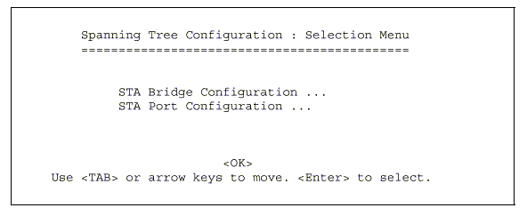
5.5.3.1 Configuring Bridge STA
The following figure and table describe Bridge STA configuration.

Parameter |
Default |
Description |
Spanning Tree Protocol |
Enabled |
Enable this parameter to participate in a STA compliant network. |
Priority |
32,768 |
Device priority is used in selecting
the root device, root port, and designated port. The device
with the highest priority becomes the STA root device. However,
if all devices have the same priority, the device with the lowest
MAC address will then become the root device. |
Hello Time |
2 |
Time interval (in seconds) at which the root device transmits a configuration message.The minimum value is1.The maximum value is the lower of 10 or [(Max. Message Age / 2) -1]. |
Max (Message) Age |
20 |
The maximum time (in seconds) a device can wait without receiving a configuration message before attempting to reconfigure. All device ports (except for designated ports) should receive configuration messages at regular intervals. Any port that ages out STA information (provided in the last configuration message) becomes the designated port for the attached LAN. If it is a root port, a new root port is selected from among the device ports attached to the network. The minimum value is the higher of 6 or [2 x (Hello Time + 1)]. The maximum value is the lower of 40 or [2 x (Forward Delay - 1)]. |
Forward Delay |
15 |
The maximum time (in seconds) the root device will wait before changing states (i.e., listening to learning to forwarding). This delay is required because every device must receive information about topology changes before it starts to forward frames. In addition, each port needs time to listen for conflicting information that would make it return to a blocking state; otherwise, temporary data loops might result. The maximum value is 30. The minimum value is the higher of 4 or [(Max. Message Age / 2) + 1]. |
5.5.3.2 Configuring STA for Ports
The following figure and table describe port STA configuration.
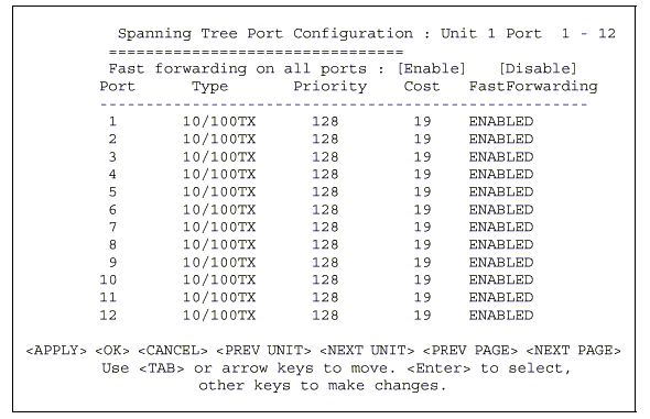
Parameter |
Default |
Description |
Fast forwarding on all ports |
Enabled |
See "FastForwarding" in this table. |
Type |
|
Shows port type as: |
Priority |
128 |
Defines the priority for the use of a port in the STA algorithm. If the path cost for all ports on a switch are the same, the port with the highest priority (i.e., lowest value) will be configured as an active link in the Spanning Tree. Where more than one port is assigned the highest priority, the port with lowest numeric identifier will be enabled. The range is 0 - 255. |
(Path) Cost |
100/19/4 |
This parameter is used by the STA algorithm
to determine the best path between devices. Therefore, lower
values should be assigned to ports attached to faster media,
and higher values assigned to ports with slower media. (Path
cost takes precedence over port priority.) |
Fast Forwarding |
Enabled |
This parameter is used to enable/disabled the Fast Spanning Tree mode for the selected port. In this mode, ports skip the Blocked, Listening and Learning states and proceed straight to Forwarding. |
NOTES: |
Fast Forwarding enables end-node workstations and servers to overcome time-out problems when the Spanning Tree Algorithm is implemented in a network. Therefore, Fast Forwarding should only be enabled for ports connected to an end-node device. |
5.5.4 Viewing the Current Spanning Tree Information
The Spanning Tree Information screen displays
a summary of the STA information
for the overall bridge or for a specific port. To make any changes to the parameters
for the Spanning Tree, use the Spanning Tree Configuration menu.

5.5.4.1 Displaying the Current Bridge STA
The parameters shown in the following figure and table describe the current Bridge STA Information.

Parameter |
Description |
Priority |
Device priority is used in selecting the root device, root port, and designated port. The device with the highest priority becomes the STA root device. However, if all devices have the same priority, the device with the lowest MAC address will then become the root device. |
Hello Time |
The time interval (in seconds) at which the root device transmits a configuration message. |
Max Age |
The maximum time (in seconds) a device can wait without receiving a configuration message before attempting to reconfigure. |
Forward Delay |
The maximum time (in seconds) the root device will wait before changing states (i.e., listening to learning to forwarding). |
Hold Time |
The minimum interval between the transmission of consecutive Configuration BPDUs. |
Designated Root |
The priority and MAC address of the device in the Spanning Tree that this switch has accepted as the root device. |
Root Cost |
The path cost from the root port on this switch to the root device. |
Root Port |
The number of the port on this switch that is closest to the root. This switch communicates with the root device through this port. If there is no root port, then this switch has been accepted as the root device of the Spanning Tree network. |
Reconfig Count |
The number of times the Spanning Tree has been reconfigured. |
Topology Up Time |
The time since the Spanning Tree was last reconfigured. |
5.5.4.2 Displaying the Current STA for Ports
The parameters shown in the following figure and table are for port STA Information.
Parameter |
Description |
|
Type |
Shows port type as: |
|
Status |
Displays current state of this port within the Spanning Tree: |
|
Broken |
No link has been established on this port. |
|
Disabled |
Port has been disabled by the user or has failed diagnostics. |
|
Blocking |
Port receives STA configuration messages, but does not forward packets. |
|
Listening |
Port will leave blocking state due to topology change, starts transmitting configuration messages, but does not yet forward packets. |
|
Learning |
Port has transmitted configuration messages for an interval set by the Forward Delay parameter without receiving contradictory information. Port address table is cleared, and the port begins learning addresses. |
|
Forwarding |
The port forwards packets, and continues learning addresses. |
|
The rules defining port status are:
|
||
Designated Cost |
The cost for a packet to travel from this port to the root in the current Spanning Tree configuration. The slower the media, the higher the cost. |
|
Designated Bridge (ID) |
The priority and MAC address of the device through which this port must communicate to reach the root of the Spanning Tree. |
|
Designated Port (ID) |
The priority and number of the port on the designated bridging device through which this switch must communicate with the root of the Spanning Tree. |
|
5.5.5 Using a Mirror Port for Analysis
You can mirror traffic from any source port to a target port for real-time analysis. You can then attach a logic analyzer or RMON probe to the target port and study the traffic crossing the source port in a completely unobtrusive manner. When mirroring port traffic, note that the target port must be included in the same VLAN as the source port. (See "Configuring Virtual LANs" .) You can use the Mirror Port Configuration screen to designate a single port pair for mirroring as shown below.
Parameter |
Description |
Mirror Source Port |
The port whose traffic will be monitored. |
Mirror Target Port |
The port that will duplicate or "Mirror"all the traffic happening on the monitored port. |
Status |
Enables or disables the mirror function. |
Port trunks can be used to increase the bandwidth of a network connection or to ensure fault recovery. You can configure up to four trunk connections (combining 2~4 ports into a fat pipe) between any two SGSW-2403 switches. However, before making any physical connections between devices, use the Trunk Configuration menu to specify the trunk on the devices at both ends.
When using a port trunk, note that:
You can use the Port Trunking Configuration screen set up port trunks as shown below:
Parameter |
Description |
Trunk ID |
Configure up to four trunks per switch. |
Status |
Shows if the selected trunk is enabled or disabled. |
Unit* |
Specifies a switch unit in the stack (1~4). |
Port |
Select from 2 ~ 4 ports per trunk. |
[Show] |
Displays trunk settings, where the first trunk listed is specified by �Trunk ID. |
[More] |
Scrolls through the list of configured trunks. |
[Enable] [Disable] |
Enables/disables the selected trunk. |
[Add] [Delete] |
Adds/deletes the port specified by Trunk ID / Member Unit / Member Port. |
The RJ-45 ports used for one side of a trunk
must all be on the same internal switch chip. The port groups permitted include:
Switch Model |
Group 1 |
Group 2 |
Group 3 |
SGSW-2403 |
1,2,3,4, 13,14,15,16 |
5,6,7,8, 17,18,19,20 |
9,10,11,12, 21,22,23,24 |
The 100BASE-FX fiber ports used for one side of a trunk must all be on the same
module. However, the 1000BASE-SX ports used for one side of a trunk may
be on any switch in the stack, or both on the same switch if used standalone.
Media Module |
|
100BASE-FX |
Any ports on a single module. |
1000BASE-SX |
Up to four Gigabit ports from any switch in the stack, or both Gigabit ports on two modules installed in a standalone switch. |
For example, when using Gigabit ports to form a trunk within a stack, the Gigabit
ports will all be at Port 25. In this case, you could specify a trunk group
consisting of: (Unit1-Port25, Unit2-Port25, Unit3-Port25, Unit4-Port25),
or two trunks consisting of: (Unit1-Port25, Unit2-Port25) and (Unit3-Port25,
Unit4-Port25).
5.5.7 IGMP Multicast Filtering
Multicasting is used to support real-time applications such as video conferencing or streaming audio. A multicast server does not have to establish a separate connection with each client. It merely broadcasts its service to the network, and any hosts which want to receive the multicast register with their local multicast switch/ router. Although this approach reduces the network overhead required by a multicast server, the broadcast traffic must be carefully pruned at every multicast switch/router it passes through to ensure that traffic is only passed on the hosts which subscribed to this service.
This switch uses IGMP (Internet Group Management Protocol) to query for any attached hosts who want to receive a specific multicast service. The switch looks up the IP Multicast Group used for this service and adds any port which received a similar request to that group. It then propagates the service request on to any neighboring multicast switch/router to ensure that it will continue to receive the multicast service. (For more information, see "I�IGMP Protocol" on chapter 7.)
This protocol allows a host to inform its local switch/router that it wants to receive transmissions addressed to a specific multicast group. You can use the IGMP Configuration screen to configure multicast filtering shown below.
Parameter |
Description |
IGMP Status |
If enabled, the switch will monitor network traffic to determine which hosts want to receive multicast traffic. This is also referred to as IGMP Snooping. |
Act as IGMP Querier |
If enabled, the switch can serve as the "querier," which is responsible for asking hosts is they want to receive multicast traffic. (Not available for the current firmware release.) |
IGMP Query Count |
The maximum number of queries issued for which there has been no response before the switch takes action to solicit reports. |
IGMP Report Delay |
The time (in minutes) between receiving an IGMP Report for an IP multicast address on a port before the switch sends an IGMP Query out that port and removes the entry from its list. |
NOTE: |
The default values are indicated in the sample screen. |
5.5.8 Configuring Bridge MIB Extensions
The Bridge MIB includes extensions for managed devices that support Traffic Classes and Virtual LANs. To display and configure these extensions, use the Extended Bridge Configuration screen as shown below.
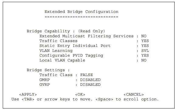
Parameter |
Description |
Bridge Capability |
|
Extended Multicast Filtering Services |
This switch does not support filtering of individual multicast addresses based on GMRP (GARP Multicast Registration Protocol). |
Traffic Classes |
This switch provides mapping of user priorities to multiple traffic classes. (Refer to "802.1p Port Traffic Class Information" .) |
Static Entry Individual Port |
This switch allows static filtering for unicast and multicast addresses. (Refer to Network Monitor Menu / Static Unicast Address Table Configuration and Static Multicast Address Table Configuration.) |
VLAN Learning |
This switch uses Shared VLAN Learning (SVL), whereby the VLAN filtering database is shared among all ports. |
Configurable PVID Tagging |
This switch allows you to override the default PVID (Port VLAN ID) assigned to untagged incoming frames under "802.1Q VLAN Port Configuration" . |
Local VLAN Capable |
This switch does not support multiple local bridges (that is, multiple Spanning Trees). |
Bridge Settings |
|
Traffic Class* |
Multiple traffic classes are supported by this switch as indicated under Bridge Capabilities. However, the switch supports just two priority queues and only the default port priority can be configured. The switch does not support the configuration of traffic class mapping. Therefore, this parameter under Bridge Settings is set to False and cannot be enabled. |
GMRP* |
GARP Multicast Registration Protocol
(GMRP) allows network devices to register endstations with multicast
groups. |
GVRP* |
GARP VLAN Registration Protocol (GVRP) defines a way for switches to exchange VLAN information in order to register necessary VLAN members on ports across the network. This function should be enabled to permit VLANs groups which extend beyond the local switch. |
* Not enabled in this firmware release.
5.5.9 Configuring Traffic Classes
IEEE 802.1p defines up to 8 separate traffic classes. This switch supports Quality of Service (QoS) by using two priority queues, with Weighted Fair Queuing for each port. You can use the 802.1P Configuration menu to configure the default priority for each port, or to display the mapping for the traffic classes as described in the following sections.

5.5.9.1 Port Priority Configuration
Inbound frames that do not have any VLAN tags
are tagged with the input port�s default VLAN ID (PVID) and the Default Ingress
User Priority as shown in the following menu, and then sorted into the appropriate
priority queue at the output port. (Note that if the output port is an untagged
member of the associated VLAN, these frames are stripped of all VLAN tags prior
to transmission.)
The default priority for all ingress ports is zero. Therefore,
any inbound frames that do not have priority tags will be placed in the low
priority queue of the output port. You can use the following menu to adjust
default ingress priority for any port as shown below.

Parameter |
Description |
Port |
Numeric identifier for switch port. |
Default Ingress User Priority |
Default ingress priority can be set to any value from 0~7, where 0~3 specifies the low priority queue and 4~7 specifies the high priority queue. |
Number of Egress Traffic Classes |
Indicates that this switch supports two priority output queues. |
5.5.9.2 802.1p Port Traffic Class Information
This switch provides two priority levels with Weighted Fair Queuing for port egress. This means that any frames with a priority tag from 0~3 are sent to the low priority queue "0" while those from 4~7 are sent to the high priority queue "1" as shown in the following screen.
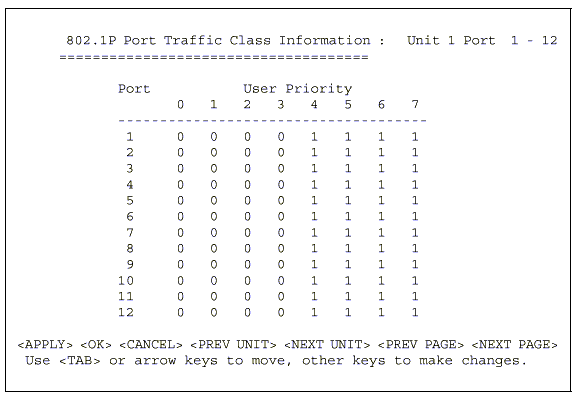
Parameter |
Description |
Port |
Numeric identifier for switch port. |
User Priority |
Shows that user priorities 0~3 specify the low priority queue and 4~7 specify the high priority queue. |
5.5.A Configuring Virtual LANs
You can use the VLAN configuration menu to assign any port on the switch to any of up to 255 LAN groups. In conventional networks with routers, broadcast traffic is split up into separate domains. Switches do not inherently support broadcast domains. This can lead to broadcast storms in large networks that handle traffic such as IPX or NetBeui. By using IEEE 802.1Q compliant VLANs, you can organize any group of network nodes into separate broadcast domains, confining broadcast traffic to the originating group. This also provides a more secure and cleaner network environment. For more information on how to use VLANs, see "Virtual LANs". The VLAN configuration screens are described in the following sections.
5.5.A.1 802.1Q VLAN Base Information
The 802.1Q VLAN Base Information screen displays basic information on the VLAN type supported by this switch.
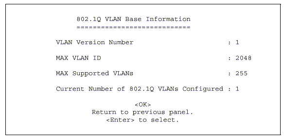
Parameter |
Description |
VLAN Version Number |
The VLAN version used by this switch as specified in the IEEE 802.1Q standard. |
MAX VLAN ID |
Maximum VLAN ID recognized by this switch. |
MAX Supported VLANs |
Maximum number of VLANs that can be configured on this switch. |
Current Number of VLANs Configured |
The number of VLANs currently configured on this switch. |
5.5.A.2 802.1Q VLAN Current Table Information
This screen shows the current port members of each VLAN and whether or not the port supports VLAN tagging. Ports assigned to a large VLAN group that crosses several switches should use VLAN tagging. However, if you just want to create a small port-based VLAN for one or two switches, you can assign ports to the same untagged VLAN. The current configuration is shown in the following screen.
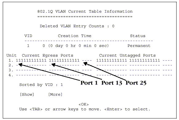
Parameter |
Description |
Deleted VLAN Entry Counts |
The number of times a VLAN entry has been deleted from this table. |
VID |
The ID for the VLAN currently displayed. |
Creation Time |
The value of sysUpTime (System Up Time) when this VLAN was created. |
Status |
Shows how this VLAN was added to
the switch. |
Unit* |
Stack unit. |
Current Egress Ports |
Shows the ports which have been added to the displayed VLAN group, where "1" indicates that a port is a member and "0" that it is not. |
Current Untagged Ports |
If a port has been added to the displayed VLAN (see Current Egress Ports), its entry in this field will be "1" if the port is untagged or "0"if tagged. |
Sorted by VID |
The VLAN ID number from which the display will start. |
[Show] |
Displays the members for the VLAN indicated by the �Sorted by VID?field. |
[More] |
Displays any subsequent VLANs if configured. |
5.5.A.3 802.1Q VLAN Static Table Configuration
Use this screen to create a new VLAN or modify the settings for an existing VLAN. You can add/delete port members for a VLAN from any unit in the stack as a tagged or untagged member. Or you can prevent a port from being automatically added to a VLAN by the GVRP protocol.
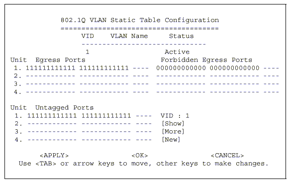
Parameter |
Description |
VID |
The ID for the VLAN currently displayed. |
VLAN Name |
A user-specified symbolic name
for this VLAN. |
Statusr |
Sets the current editing status for this VLAN as: Not in Service, Destroy or Active. |
Unit* |
Stack unit. |
Egress Ports |
Set the entry for any port in this field to "1" to add it to the displayed VLAN, or "0" to remove it from the VLAN. |
Forbidden Egress Ports |
Prevents a port from being automatically added to this VLAN via GVRP. Note that GVRP is not supported in the current firmware release. |
Untagged Ports |
You can add a port to the displayed VLAN as an untagged port by setting this field to "1" or as a tagged port by setting it to "0" This field is only enabled if the corresponding port has been added to the displayed VLAN as an "Egress Port." |
[Show] |
Displays settings for the specified VLAN. |
[More] |
Displays consecutively numbered VLANs. |
[New] |
Sets up the screen for configuring a new VLAN. |
For example, the following screen displays settings for VLAN 2, which includes
untagged ports 1-6, and forbidden port 8.

NOTES: |
|
5.5.A.4 802.1Q VLAN Port Configuration
Use this screen to configure port-specific settings for IEEE 802.1Q VLAN features.
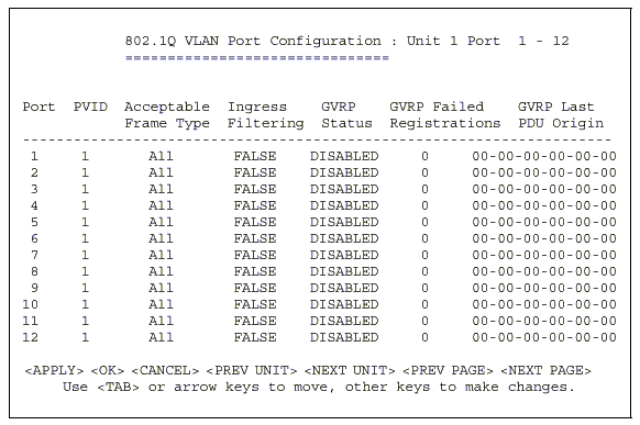
Parameter |
Description |
PVID |
The VLAN ID assigned to untagged frames received on this port. |
Acceptable Frame Type 1 |
This switch accepts"A�All" frame types, including VLAN tagged or VLAN untagged frames. Note that all VLAN untagged frames received on this port are assigned to the PVID for this port. |
Ingress Filtering 1 |
If set to "True",incoming frames for VLANs which do not include this ingress port in their member set will be discarded at the ingress port. |
GVRP Status 2 |
Enables or disables GVRP for this port.
When disabled, any GVRP packets received on this port will be
discarded and no GVRP registrations will be propagated from
other ports. |
GVRP Failed Registrations 2 |
The total number of failed GVRP registrations, for any reason, on this port. |
GVRP Last PDU Origin 2 |
The Source MAC Address of the last GVRP message received on this port. |
NOTES: |
|
The Network Monitor Menu provides access to port statistics, RMON statistics, IP multicast addresses, and the static address table. Each of the screens provided by these menus is described in the following sections.

Parameter |
Description |
Port Statistics |
Displays statistics on network traffic passing through the selected port. |
RMON Statistics |
Displays detailed statistical information for the selected port such as packet type and frame size counters. |
Unicast Address Table |
Provides full listing of all unicast addresses stored in the switch, as well as sort, search and clear functions. |
Multicast Address Registration Table* |
Displays the ports that belong to each GMRP Multicast group. |
IP Multicast Registration Table |
Displays the ports that belong to each IP Multicast group. |
Static Unicast Address Table Configuration |
Allows you to display or configure static unicast addresses. |
Static Multicast Address Table Configuration* |
Allows you to display or configure static GMRP multicast addresses. |
* Not implemented in this firmware release.
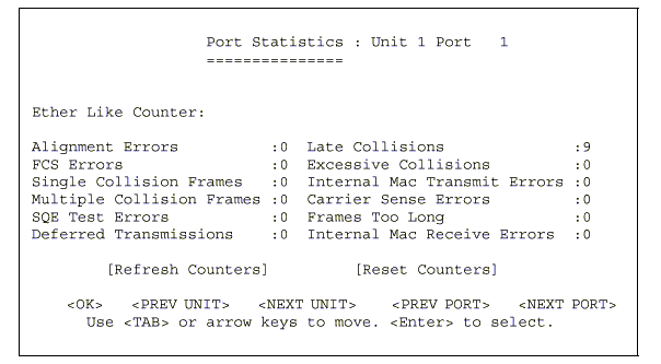
5.6.1 Displaying Port Statistics
Port Statistics display key statistics from the Ethernet-like MIB for each port. Error statistics on the traffic passing through each port are displayed. This information can be used to identify potential problems with the switch (such as a faulty port or unusually heavy loading). The values displayed have been accumulated since the last system reboot.
Select the required port. The statistics displayed are indicated in the following figure and table.
Menu |
Description |
Alignment Errors |
The number of alignment errors (mis-synchronized data packets). |
FCS Errors |
The number of frames received that are an integral number of octets in length but do not pass the FCS check. |
Single Collision Frames* |
The number of successfully transmitted frames for which transmission is inhibited by exactly one collision. |
Multiple Collision Frames* |
A count of successfully transmitted frames for which transmission is inhibited by more than one collision. |
SQE Test Errors* |
A count of times that the SQE TEST ERROR message is generated by the PLS sublayer. |
Deferred Transmissions* |
A count of frames for which the first transmission attempt on a particular interface is delayed because the medium was busy. |
Late Collisions |
The number of times that a collision is detected later than 512 bit-times into the transmission of a packet. |
Excessive Collisions* |
The number of frames for which transmission failed due to excessive collisions. |
Internal Mac Transmit Errors* |
The number of frames for which transmission failed due to an internal MAC sublayer transmit error. |
Carrier Sense Errors* |
The number of times that the carrier sense condition was lost or never asserted when attempting to transmit a frame. |
Frames Too Long |
The number of frames received that exceed the maximum permitted frame size. |
Internal Mac Receive Errors* |
The number of frames for which reception failed due to an internal MAC sublayer receive error. |
* The reported values will
always be zero because these statistics are not supported by the internal
chip set
.
NOTES: |
Statistics are automatically refreshed every 5 seconds (refer to "Configuring the Serial Port" section.). |
5.6.2 Displaying
RMON Statistics
Use the RMON Statistics screen to display key statistics
for each port from RMON group 1. (RMON groups 2, 3 and 9 can only be accessed
using SNMP management software such as SNMPc.) The following screen displays
the overall statistics on traffic passing through each port. RMON statistics
provide access to a broad range of statistics, including a total count of different
frame types and sizes passing through each port. Values displayed have been
accumulated since the last system reboot.

Menu |
Description |
Drop Events |
The total number of events in which packets were dropped due to lack of resources. |
Received Bytes |
Total number of bytes of data received on the network. This statistic can be used as a reasonable indication of Ethernet utilization. |
Received Frames |
The total number of frames (bad, broadcast and multicast) received. |
Broadcast Frames |
The total number of good frames received that were directed to the broadcast address. Note that this does not include multicast packets. |
Multicast Frames |
The total number of good frames received that were directed to this multicast address. |
CRC/Alignment Errors |
The number of CRC/alignment errors (FCS or alignment errors). |
Undersize Frames |
The total number of frames received that were less than 64 octets long (excluding framing bits, but including FCS octets) and were otherwise well formed. |
Oversize Frames |
The total number of frames received that were longer than 1518 octets (excluding framing bits, but including FCS octets) and were otherwise well formed. |
Fragments |
The total number of frames received that were less than 64 octets in length (excluding framing bits, but including FCS octets) and had either an FCS or alignment error. |
Jabbers |
The total number of frames received that were longer than 1518 octets (excluding framing bits, but including FCS octets), and had either an FCS or alignment error. |
Collisions |
The best estimate of the total number of collisions on this Ethernet segment. |
64 Byte Frames |
The total number of frames (including bad packets) received and transmitted that were 64 octets in length (excluding framing bits but including FCS octets). |
65-127 Byte Frames |
The total number of frames (including bad packets) received and transmitted that were between 65 and 127 octets in length inclusive (excluding framing bits but including FCS octets). |
128-255 Byte Frames |
The total number of packets (including bad packets) received and transmitted that were between 128 and 255 octets in length inclusive (excluding framing bits but including FCS octets). |
1024-1518 Byte Frames |
The total number of packets (including bad packets) received and transmitted that were between 1024 and 1518 octets in length inclusive (excluding framing bits but including FCS octets). |
NOTES: |
Statistics are automatically refreshed every 5 seconds (refer to "Configuring the Serial Port" section.). |
5.6.3 Displaying the Unicast Address Table
The Address Table contains the MAC addresses and VLAN identifier associated with each port (that is, the source port associated with the address and VLAN), sorted by MAC address or VLAN ID. You can search for a specific address, clear the entire address table, or information associated with a specific address, or set the aging time for deleting inactive entries. The information displayed in the Address Table is indicated in the following figure and table.
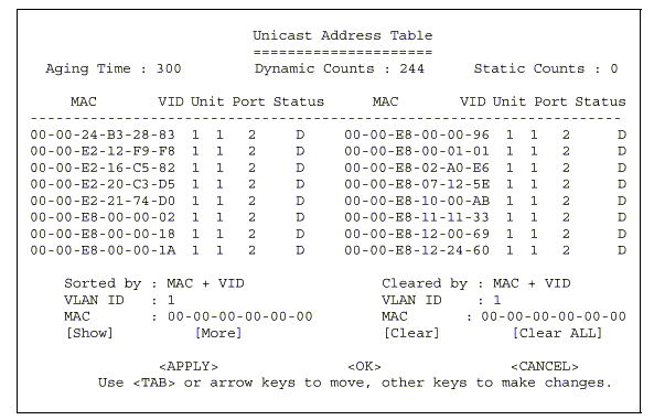
Description |
|
Aging Time |
Time-out period in seconds for aging
out dynamically learned forwarding information. |
Dynamic Count |
The number of dynamically learned addresses in the table. |
Static Count |
The number of static addresses in the table. |
MAC |
The MAC address of a node. |
VID |
The VLAN(s) associated with this address or port. |
Unit* |
Switch unit in the stack (1~4). |
Port |
The port whose address table includes this MAC address. |
Status |
Indicates address status as: |
Sorted/Cleared by |
Selects the primary key used to sort/clear the table: MAC or VID. |
[Show] |
Displays the address table for the specified VLAN ID, sorted by primary key MAC or VID. |
[More] |
Scrolls through the entries in the address table. |
[Clear] |
Clears the specified MAC address. |
[Clear All] |
Clears all MAC addresses in the table. |
5.6.4 Displaying the IP Multicast Registration Table
Use the IP Multicast Registration Table to display all the multicast groups active on this switch, including multicast IP addresses and the corresponding VLAN ID.

Menu |
Description |
VID |
VLAN ID assigned to this multicast group. |
Multicast IP |
IP address for specific multicast services. |
Unit* |
Stack unit. |
Dynamic Port Lists |
The switch ports registered for the indicated multicast service. |
Learned by |
Indicates the manner in which this address was learned: Dynamic or IGMP. |
Sorted by |
Selects the primary sort key for displaying table entries. Note that only VID+Multicast IP is implemented in the current firmware release. |
[Show] |
Displays the address table sorted on VID and then Multicast IP. |
[More] |
Scrolls through the entries in the address table. |
5.6.5 Configuring Static Unicast Addresses
Use the Static Unicast Address Table Configuration screen to manually configure host MAC addresses in the unicast table. You can use this screen to associate a MAC address with a specific VLAN ID and switch port as shown below.

Menu |
Description |
|||||||
VID |
The VLAN group this port is assigned to. |
|||||||
MAC Address |
The MAC address of a host device attached to this switch. |
|||||||
Unit* |
The switch unit the host device is attached to. |
|||||||
Port |
The port the host device is attached to. |
|||||||
Status |
The status for an entry can be set to: |
|||||||
Permanent |
This entry is currently in use and will remain so after the next reset of the switch |
|||||||
DeleteOnReset |
This entry is currently in use and will remain so until the next reset. |
|||||||
Invalid |
Removes the corresponding entry. |
|||||||
DeleteOnTimeOut |
This entry is currently in use and will remain so until it is aged out. (Refer to "Aging Time".) |
|||||||
Other |
This entry is currently in use but the conditions under which it will remain so differ from the preceding values. |
|||||||
Sorted by |
Selects the primary sort key for displaying table entries. Note that only VID+MAC is implemented in the current firmware release. |
|||||||
[Show] |
Displays the static address table sorted on VID as the primary key and MAC address as secondary key. |
|||||||
[More] |
Scrolls through entries in the static address table. |
|||||||
[Set] |
Adds the specified entry to the static
address table, such as shown in the following example:
|
|||||||
Use the Restart command under the Main Menu to reset the management agent. The reset screen includes options as shown in the following figure and table.
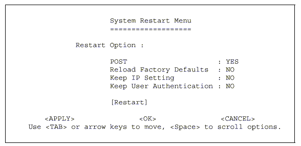
Menu |
Description |
POST |
Runs the Power-On Self-Test |
Reload Factory Defaults |
Reloads the factory defaults |
Keep IP Setting |
Retains the settings defined in the IP Configuration menu. |
Keep User Authentication |
Retains the user names and passwords defined in the Console Login Configuration menu. |
[Restart] |
Restarts the switch. |
Use the Exit command under the Main Menu to exit the configuration program and terminate communications with the switch for the current session.
|
|
|
Copyright (c) 2001, Planet Technology Corp. |